Translate

Thursday, September 26, 2013

New US Mediumwave Files Uploaded

A new US Mediumwave Pattern Reference, produced by Radio Data MW, has been uploaded. You will find it at the top of the right sidebar under LATEST US MEDIUMWAVE FILES. Radio Data MW, a program I have been working on for the last few years, accomplishes this mapping process.

Included is a complete set of GoogleMap-based, HTML-driven maps which show the most current pattern plots of all licensed US mediumwave broadcast stations from 540 - 1700 KHz. The set includes all frequencies for the indicated services: Unlimited, Daytime, Nighttime, and Critical Hours. Individual maps are grouped by channel frequency: 540, 550, 560 KHz, etc.

DOWNLOAD

See the link at the top of the right sidebar under LATEST US MEDIUMWAVE FILES.

I will attempt to make this a regular feature on RADIO-TIMETRAVELLER, with regular yearly updates. The sidebar at the top right will have the most current links. The link will change for each new posting, so I would avoid copying and pasting it into a forum or other web page. Come to the main page of this blog instead.

INSTALLING

The maps are HTML-based, so no regular install is necessary. Simply unzip the downloaded file and click on the individual map file to run. The map will open up in your web browser. They are self-contained, with image icons embedded right into the code. You must have an internet connection to view the maps.

HOW THEY ARE PRODUCED

Using the actual FCC database files Radio Data MW will auto-generate an interactive HTML pattern map, showing the pattern plots for all stations included at the discretion of the user. A complete set of mediumwave pattern maps can be generated in a matter of minutes. Radio Data MW generates a real pattern plot based on ground conductivity, ground dielectric constant, and can display actual (but approximate of course) signal level boundaries for Local, Distant, Fringe, Extreme mV/m levels, or any custom mV/m level chosen by the user.

The online Google Maps API is used to generate and plot each station on a map of the US. An accurate flag pin is placed at each transmitter location, and in satellite view may be zoomed in to see the actual transmitter site. Map flags are color-coded to indicate Unlimited, Daytime, Nighttime, and Critical Hours services. Each flag has a tooltip-type note, and when hovered over with the mouse will display a note on the station.

A pattern plot for each station is generated and displayed. Each pattern is calculated using standard formulas used by the FCC to compute the base values at one kilometer, and field strength formulas at distance based on the works of many people over the years. See Field Strength Calculations: A History and Field Strength Calculator One, previously posted on RADIO-TIMETRAVELLER.

Finally, an accurate ray path can be drawn from all transmitters to a user-specified receiving location by inputting latitude-longitude coordinates. Super-imposed on the pattern plots, the ray paths show the listener where he or she falls on each station's pattern, a handy guide to knowing where you stand.

Note that these maps are web-based. As stated, they use Google Maps and thus require access to Google. In order to view them you need a connection to the internet. In desktop or laptop use, they have been tested in the Internet Explorer, Firefox, Chrome, Opera, and Safari browsers. If using Internet Explorer, best results are had with the latest version. Chrome works best.

These maps will work on some tablet or phone browsers. I have tested them on an Android device and it's handy to be able to display them while DXing outside or on the road. Some browsers will not allow pinch-to-zoom, where others will. Some browsers don't render the map controls correctly. Response is fair to poor on the tablet or phone due to the sheer number of HTML lines and processing required to render the maps. Such is the current state of tablet and phone browser rendering.

Hope you enjoy these pattern maps and find them useful.

Tuesday, August 27, 2013

Loop Calculator One: Update 1.0228

The latest update to Loop Calculator One includes various cosmetic updates to improve readability and understandability.

For those new to Loop Calculator One, the program will display detailed information about coils, including accurate inductance for short and long coils of many types. It is especially tailored for inductance calculations of polygonal-shaped mediumwave receiving loops.

The original Loop Calculator One article was published on RADIO-TIMETRAVELLER in March, 2012.

For further information on loop calculations see the Loop Calculations Series previously published on RADIO-TIMETRAVELLER.

DOWNLOAD

To download, see the link at the top of the right sidebar under LATEST PROGRAMS. The sidebar at the top right will have the most current link in case the program is updated. The link will change in the case of an update, so I would avoid copying and pasting it into a forum or other web page. Come to the main page of this blog instead.

INSTALL

Install is simple. Download the .zip file and unzip. Click on the LoopCalculatorOne.exe file to run. This program makes no registry changes and saves no data to your hard drive. It has been developed and tested in Windows 7. It should work fine in Windows Vista and XP environments, and Windows 8. It is written in the old standby Visual Basic 6.

Included in the .zip is a readme.txt file. Be sure to have a look. Also included is an American Wire Gauge chart showing wire diameters.

Click image to enlarge.


Field Strength Calculator One: Update 1.0054

The latest update to Field Strength Calculator One has corrected the About window and incorporated various cosmetic updates. Also included are further refinements to the accuracy of the field strength calculation and distances.

For those new to Field Strength Calculator One, the program returns expected received field strength in millivolts per meter and dBu (also known as dBµV/m), based on ground conductivity, earth dielectric and several other input constants. It also displays the distance to the radio horizon and the signal path loss in dB, along with several more technical parameters. The resulting output of Field Strength Calculator One should be accurate in most cases to a couple of percent in the longwave and mediumwave bands. It compares favorably to ITU program GRWAVE and currently available FCC Ground Wave Conductivity graphs.

The original Field Strength Calculator One article was published on RADIO-TIMETRAVELLER in December, 2012.

For further information on how field strength is calculated see the Field Strength Calculations Series previously published on RADIO-TIMETRAVELLER.

DOWNLOAD

To download, see the link at the top of the right sidebar under LATEST PROGRAMS. The sidebar at the top right will have the most current link in case the program is updated. The link will change in the case of an update, so I would avoid copying and pasting it into a forum or other web page. Come to the main page of this blog instead.

INSTALL

Install is simple. Download the .zip file and unzip. Click on the FieldStrengthCalculatorOne.exe file to run. This program makes no registry changes and saves no data to your hard drive. It has been developed and tested in Windows 7. It should work fine in Windows Vista and XP environments, and Windows 8. It is written in the old standby Visual Basic 6.

Included in the .zip is a readme.txt file. Be sure to have a look.

Click image to enlarge.


Wednesday, July 31, 2013

National Radio Club Antenna Pattern Book - 7th Edition


I wasn't sure a new edition of this book would ever be published again, but here it is.

*Note: Can't seem to find this book as of July, 2018. Perhaps it is out of publication.

New for 2013, the National Radio Club Antenna Pattern Book - 7th Edition.

This all new edition prepared by NRC’er Paul Swearingen is an all-inclusive book of patterns for both Day and Night operation of stations in the USA, Canada and selected foreign stations. The data for this comes from the forthcoming 34th edition of the AM Radio Log and NRC’er John Callerman’s comprehensive Mexican Station listing.

The book comes shrink wrapped in 8.5 by 11 three hole punch format for placement in your own three ring binder. There are 240 pages and the book has maps covering 530 through 1700 Kilo Hertz depicting the lower USA, Canada and Mexico. Hawaii and Alaska are shown on separate maps at the of the book.

The book is available from the National Radio Club at PO Box 473251, Aurora CO 80047 and ships media Rate to addresses in the United States for $22.95 for members ($26.80 shipped priority mail) and $28.95 ($32.80 shipped priority mail) for nonmembers. Canadian orders are US$35.00 and all other countries are US$39.00 both shipped Global Priority Mail.

The book will begin shipping immediately following the Minneapolis Convention, August 1-4.

Friday, June 28, 2013

Review Of The Tecsun R2010D DSP Receiver

       -With emphasis on mediumwave reception
       -And comparisons to various radios

       -by RADIO-TIMETRAVELLER

       Purchased From: Anon-co (eBay)
       Price: $28.99 + $10.00 shipping ($38.99 total)

       Serial#: 41420130600004 06/2013

Tecsun R2010D DSP receiver

INTRODUCTION

The R2010D DSP Receiver is the newest Tecsun DSP offering now available for shipping to the United States. It tunes the mediumwave, shortwave, and FM bands, and is built around the Silicon Labs Si484x DSP receiver chip. The Si4840/44 is the first analog-tuned, digital CMOS AM/FM/SW radio receiver IC with digital display capabilities that integrates the complete receiver function from antenna input to audio output. This chip has been out for a couple of years now, but this is the first application to appear in a working unit available to the US.

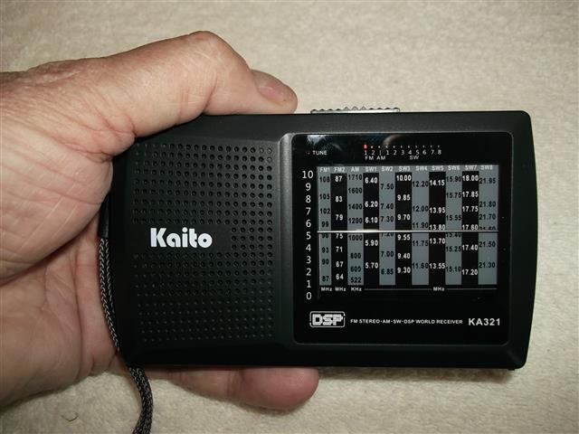
Note, this is not the same chip employed in the recent Tecsun DE321 or Kaito KA321 units which are based on the Si483x chip series, another mechanically-tuned, digital CMOS AM/FM/SW radio receiver IC. That chip series, though using the same software base, does not have digital display capability.

In Silicon Labs words, "...the Si4840/44 delivers superior RF performance and interference rejection...this patented architecture allows for high-precision filtering, offering excellent selectivity and SNR with minimum variation across the AM band...the Si4840/44-A10 optimizes sensitivity and rejection of strong interferers, allowing better reception of weak stations." Let's see how well this radio meets these claims.

This review is purposely slanted toward the mediumwave DX enthusiast, mainly because I am one and that's why I bought this radio: to further pursue this hobby of mediumwave DX. Much of what is said in terms of functionality and technical specification can also be applied to the shortwave and FM sections of this radio.

Coverage:

       Longwave coverage: None
       Mediumwave coverage: 520 - 1710 KHz (9 or 10 KHz split)
       Shortwave coverage: 5600 - 22000 KHz (in 8 bands)
       FM coverage: 64 - 108 MHz (in 3 bands)

SHIPPING AND ARRIVAL

This is my second radio purchased from eBay seller Anon-co, based in Hong Kong. Anon-co does not disappoint, providing a great purchase experience. PayPal was used for the transaction. I ordered the black version. A silver version is also available for the same price.

The radio was on its way out of Hong Kong within 24 hours via air post. A tracking number was provided for the parcel, shipped by Hong Kong Post via USPS ePacket. The radio arrived half a world away in New York a short 8 days later, delivered by USPS. Shipping on this unit was only $10. As a comparison, the PL-380 I ordered from Anon-co was billed at $24.00 shipping. I found the $10 shipping rate on the R2010D to be an excellent value, and a nice reduction from the previous rate for a similarly-sized parcel.

The R2010D is a good looking unit with its rounded corners and beautiful dial face. It is larger than I expected, and is physically the same size as the Tecsun PL-600 overall. It measures out at 7-1/2 wide x 4-3/4 high x 1-1/8 deep. It will not fit in a shirt pocket and is definitely not in the ultralight category. It came packed in a bubble-wrapped Tecsun box, the box itself inside a heavy duty bubble-wrapped envelope. It arrived in good shape.

The package

ACCESSORIES

Accessories include a spartan but adequate brown-felt carrying bag with drawstring, earbuds and a manual. No batteries or USB cord are included, though the radio has a mini-USB connector on the side.

MANUAL

The manual, in Chinese, contains 17 pages. An occasional English word or phrase appears near most of the graphics which is only slightly helpful. A very nice detailed block diagram is shown just inside the front cover.

And talk about service, Anon-co surprised me with an English manual in .PDF form via e-mail just two days after receiving my radio!

SETUP

The radio requires 3 AA batteries, the same as the PL-380, and one less than the Kaito KA321. More on batteries in a bit. I encountered unusually high battery drain with this radio.

The radio came preset for the Asian mediumwave split, 9 KHz. A simple key press toggles between 9 KHz and 10 KHz splits. Hold the 9/10 KHz button down for a long second or two and the split reverses.

While powered off, the clock is set by holding the Time button down and pressing either the up or down arrow buttons. It appears the clock is locked into the 24 hour military style format. Though the tuned frequency normally shows in the small digital display while the radio is operational, the clock time can be made to show by pressing the Time button momentarily. The alarm time is shown in a similar fashion by pressing the Alarm button momentarily.

No other setup was required.

QUALITY AND ERGONOMICS

The R2010D build and fit quality is good, and about on a par with other Tecsun radios. Buttons, though few on this radio, give a nice solid click when pressed, and have a stiff spring behind them. The wide Light/Snooze button on the top of the radio at first appears to be a rocker style like the Eton E1, but is not. It's just a simple switch.

The generous telescoping whip antenna measures a full 34-1/2 when fully extended, and is stout and of nice quality. After pulling its stem out a bit, it will rotate.

Left side

On first glance, the radio sort of reminds me of an enlarged Kaito WRX911, with a similarly-styled but larger slide rule dial-face and an almost identical but larger band switch mechanism. The Kaito KA321 also used the same slide switch bandswitch setup. It gets the job done though it has a cheap feel to it. What it actually does is switch in different resistor combinations to change band selection.

The small digital display at the top left-center is 1-1/4 wide x 1/2 inch tall. It is used for displaying frequency and a few other things which will be explained below. It is backlit when you press the Light button.

A nicely-sized Power button is at the top left front. It also serves as a Sleep button to turn the radio on for a predetermined time (120-90-75-60-45-30-15-10-5-1 minutes, or full on).

Next to the Power button are a group of four buttons. One, a Time button is available to set the clock as described above. An alarm is available as a seperate button and is set similarly as the clock.

An FM Stereo button allows you to choose monaural or stereo output through the headphone jack. It also serves in secondary functions to set the AM channel split and as the "down" button for the clock.

Lastly is a Lock button to lock the few controls on the radio, and to prevent it from accidentally turning on. It also serves as the "up" button for the clock.

A large (3 inch) front-firing, round speaker is on the left front. Sound through the nicely-sized speaker is quite pleasant. A separate tone control slide switch also appears on the front allowing low-medium-high tone control, and has good range.

Right side

On the left side are mini jacks for connecting an external FM or shortwave antenna, a line input for playing audio from an external device, and a headphone jack. Also is a mini-USB connector accepting 5 volt DC input for powering the radio via USB and charging of batteries in the radio.

Two ridged, thumb-wheeled styled knobs protrude edge-wise from the right side of the radio. They are tuning and volume. The volume control is a standard pot, not detented. The tuning wheel is connected to a dial string mechanism which also drives a resistive potentiometer. Obviously, it is not detented either.

On the back of the radio is a flip stand for elevating the R2010D if set on a flat surface. The R2010D also comes with a handstrap. The battery compartment cover is not hinged, but removable. Take care not to misplace it.

DIAL DISPLAY

Your attention is immediately drawn to the dial face display. It is beautifully done. The non-LCD frequency display mimics the slide rule style of yesteryear. Twelve bands are presented. A horizontal dial marker wipes across the front of the radio from top to bottom indicating the tuned frequency. It is not backlit, but perhaps doesn't need to be since the frequency is displayed digitally in the small LCD window. Tuning is fairly smooth, with only a small amount of backlash.

You will note the frequency scales on the dial face are linear and not logarithmic like a traditional analog capacitor/coil tuned radio would be. We all remember the AM band being crammed together up above 1200 KHz on radios of old (and even new). Not on this one. The frequencies are evenly spaced on the dial face, giving more room between kilocycles at the upper end. Interpretation of the tuned frequency is made much easier.

My dial display was not quite accurate with the digital readout. 900 KHz on the dial wiper actually was tuned to 930 KHz. Not a huge difference and not a problem anyway, since the frequency is displayed in the LCD display.

THE LCD DISPLAY

The digital display on this unit is small and displays only minimal information but gets the job done.

Tune the mechanical dial and the tuned frequency is displayed instantly in the LCD window. A band indicator shows which bandset (FM, MW, SW) you are in. Also present is an "in-tune" indicator icon >|< meant to show when station tuning is properly centered. It takes a strong station to light it, however.

Long-press the Time button and the time is displayed. Ditto for the Alarm button. A bell icon shows alarm set. A crude depiction of a miniature bed shows if you are in sleep-timer mode. It took me awhile to figure that one out.

The LCD backlight can be set to "Intelligent" mode, where the backlight will turn on automatically when using the tuning dial or the switches to select the band or tone.

Finally, a small battery icon with a slash through it will show if your batteries becomes weak. It seems to trigger a little too early while the batteries still have some reserve left in them. And unfortunately, once triggered, the radio shuts down.

TUNING AND SOFT-MUTE

Tuning is fairly smooth across all bands, and "similar" to an analog radio. "Similar" is in quotes, meaning it is somewhat like the analog tuning of old, but not quite. Tecsun has made a fair attempt at reproducing the feel of analog tuning with this unit and is leaps and bounds ahead of the Tecsun DE321 and Kaito KA321 experience in terms of tuning smoothly through stations. A good effort.

On AM, the digital display does not indicate down to the preferred one kilohertz level but only the actual channel frequency. This is to be expected in a consumer radio of this price range, so I can hardly give marks off for it. Frequency step encoding on the AM broadcast band, that small amount of tuning change as the tuning wheel is rotated, is 10 KHz, unlike the 5 KHz AM step of the Kaito KA321.

The FM band is tuned in 0.1 MHz (100 KHz) steps. A good choice, as it allows you to tune in between stations since FM channels are seperated by 200 KHz.

The shortwave band is tuned in 5 KHz steps, appropriate since stations are generally spaced at this distance.

Since the radio is tuned in steps, stations suddenly "pop in" rather than slowly increasing strength as you approach their frequency while tuning. The digital display keeps up perfectly with the mechanical movement, and without lag, so you always know where you are. Care must be taken to turn the tuning wheel slowly when searching for a specific frequency, but you don't need the hands of a brain surgeon as when tuning the Kaito KA321.

Back side

Soft mute has apparently been implemented in this unit, though seems slow and erratic in its operation, acting more like AGC with an extremely slow decay time. At times, a dead channel will produce a lot of background noise, and at times is very quiet. Weak and medium-strength stations often seem to pump severely, and the conclusion is that the AGC is poorly implemented, and/or is reacting in a weird way with the soft mute. It is not a good experience. One wonders if engineering actually bothered to listen to this radio after the design stage was complete.

So soft mute is with us again it seems. Soft mute is merely a programmable function on these DSP chips, and even Silicon Labs declares in their documentation that it can be switched off by a hardware (re: button) option. Maybe next time we could have a button to disable it. They could label it "DX".

SENSITIVITY

I am disappointed by the AM broadcast band sensitivity. Overall, sensitivity on AM is approximately the same as the Kaito KA321, which was poor. In a quiet location, Buffalo, NY daytime WWKB-1520 (50KW) to the west at 69 miles was receivable only at marginal levels in headphones. Buffalo, NY daytime WGR-550 (5KW) was barely above the noise level. Syracuse, NY daytime WHEN-620 (5KW), again at 69 miles but to the east, was nowhere to be found. All of these stations are easily receivable on most radios, and come in like locals on the truck radio.

Nighttime skywave reception was also deficient. Only several hundred miles away, 50 kilowatt WWL-700 in Cincinnati, OH was uncommonly weak at 4AM in the morning though it boomed in on the PL-380 and PL-600. Even the smaller cheap radios like the Sony SRF-59 and the Sony ICF-S10MK2 recovered better signal.

FM sensitivity is good to very good, and better than some of the smaller radios I own. This could be a fairly good DX machine on FM.

Shortwave sensitivity is good, and I'm sure is somewhat helped by the long whip antenna. Extending it or connecting an external antenna would probably send this radio into shock if you are near any high powered AM stations due to image problems and desense.

Several factors may be at work here effecting AM broadcast band sensitivity. Those would be AGC, soft mute, and desense. Desense is a problem with this radio and if you are anywhere near an AM transmitter, even at several miles distant, you will notice it. I am relatively close to three stations. The closest is a 1370 KHz, 5KW station at 1.6 miles. Desense was crippling. Other radios I own are only moderately effected. Even the poorly-selective Sony ICF-M37V is less effected by desense than the R2010D.

Tuning to the opposite end of the band (towards 530 KHz, and away from the transmitter in my case) caused the desense to disappear and the background noise to increase. Curiously, the sensitivity still remained poor. So I drove out to the country as a test to get away from it all.

Out in the country and away from strong broadcast transmitters, desense disappeared and background noise came up across the entire band. Sensitivity remained poor, though slightly better. I was surprised at the amount of background noise, as if the soft mute was disengaged.

SELECTIVITY

Unfortunately, Tecsun (or should I say Silicon Labs?) has gone overboard in trying to mimic analog tuning using a digital chip. The problem? By design, stations are received not only on their primary channel but on both adjacent channels at slightly reduced volume than the primary channel, masking any weaker station which might be underneath. On AM and shortwave when approaching a station, it reminds one of the FM "capture effect", where the stronger station pops in over the weaker one, completely eliminating the weaker one. Consequently stations occupy three channels, or in the case of the R2010D, three tuning steps. This is not acceptable unless you are a casual listener only interested in strong, local stations.

One wonders how the filtering is accomplished since we effectively have a 30 KHz bandpass! No mention of hard bandwidth filters is made in either the Si484x Data Sheet or Programming Guide, though in the Si473X DSP chips multiple bandwidths were available programatically. The PL-380 had several, from 1 to 6 KHz in width. The sharp DSP "brick-wall" effect was quite good in eliminating adjacent interference, even in an extremely-strong signal environment. I would expect this chip to have similar bandwidth ability, or perhaps just a single steep-sloped DSP filter. One wonders about the adjacent channel decision in the design process.

In examining the Si484x Programming Guide, a curious setting is uncovered which may explain the selectivity problem. It is in the range of commands called ATDD_AUDIO_MODE (ATDD=Analog Tune Digital Display), specifically the value ADJPT_ATTN. ADJPT_ATTN is used to set the adjacent channel volume for both FM and AM modes, and is applied during powerup of the chip. Only two settings are available. The adjacent channels can be set for audio to be equal to the primary channel, or -2dB down (aurally hardly noticeable) from the primary channel. In actual use, medium to strong stations occupy both adjacent channels at nearly equal volume to the primary channel. So, I surmise the design-thinking was to allow a station to occupy adjacent channels at reduced volume from the primary channel in an attempt to make the pseudo-analog tuning experience more realistic.

What they have done is eliminate the possibility of receiving a weaker or even moderately-strong station that happens to be adjacent to a stronger one. At night here, it is common to hear WBZ-1030, Boston, MA (50KW) next to local WYSL-1040 (500 watts nighttime) in Avon, NY on the average radio. The R2010D cannot accomplish this, normally a simple feat - WYSL occupies 1030 KHz. Similarly during daytime hours, by rotating a radio carefully, one can normally hear Toronto's CHUM-1050 coming across Lake Ontario and adjacent to WYSL-1040. WYSL pounds in on 1050 KHz instead on the R2010D.

The Kaito KA321 which uses the sister chip to the Si484x, does not have this problem. It is programmed to use a 5 KHz internal tuning step on the AM broadcast band. If my guess is right, the result is the +/- 5 KHz frequency slot is the buffer between the adjacent channel weaker station, allowing the tuned station's audio to still taper off and be heard at +/- 5 KHz, without interfering with the adjacent channel. It's all in the programming.

Further evidence to this theory is found in a Silicon Labs FAQ for the sister chip Si483x. The R2010D's chip uses the same software set:

Question: ...is it easy to tune exactly to a station?

Answer: ...the Si4831/35 uses a new tuning algorithm that allows the user to hear one station across a larger frequency range. At the same time, the user can easily feel or tell if the tuned position is the best by the sound. The new tuning algorithm was added to improve the tuning feel and has been well received in the marketplace. The algorithm was carefully optimized such that selectivity was not compromised; therefore, weak station is still easy to tune.

It worked in the Kaito KA321 but is broken in the Tecsun R2010D.

Internal

ANTENNAS

The R2010D comes with a 4-5/8 inch ferrite loopstick, slightly longer than even the PL-600, a radio with excellent sensitivity. The radio couples well to an external passive loop antenna. When doing so, the extra signal strength caused severe AGC pumping. Receiver desense was also increased.

SIGNAL SPURS AND IMAGES

Shortwave is marred by occasional images and AM broadcast bleed-through if you are in a strong signal area. This is not the radio to own if you are anywhere near medium to high power AM stations.

NOISE IMMUNITY

Noise immunity seems good compared to most radios. Move two or three feet from an external noise source and RFI generally disappears. Too, the digital display on this radio is so small that it contributes little noise as well. Purely digital sets are usually worse.

BATTERY LIFE

Battery life was a disappointment on my radio. Battery life should be good on this unit, as the chip requirements are about the same as the PL-380 and Kaito KA321. Published specs I have seen for the R2010D indicate an average consumption with radio switched-on (at zero or low volume) to be only about 25ma. Within a 52 hour span, and totaling only about four hours of switched-on listening time, using headphones, I went through not one but two sets of batteries (6 alkaline AAs total).

Out of curiousity, I took my digital meter out and measured the current draw. Totally turned off, the radio drew a whopping 63mA. Turned on, at zero volume and not tuned to a station it drew 84mA. Turned on, at zero volume and tuned to a station it drew 100-150mA. No wonder the batteries failed so soon in my unit. Each set lasted about 24 hours.

As a comparison, the Kaito KA321 using a similar chip measures zero mA when powered off, 21mA at idle, and 40-100mA when tuned to a station.

SUMMATION

I had hoped this radio would finally bring us a sensitive and selective analog-like radio in a digital package. It has not. Though Tecsun has been able to very nearly simulate the analog tuning experience, engineering deficiencies and/or poor software setup cause problems in several other areas. Sensitivity is lacking and shouldn't be, considering the chip's datasheet sensitivity specs are almost identical with the PL-380's and a 4+ inch loopstick has been employed. Weirdness in the selectivity design or setup results in an effective 30 KHz wide bandpass which causes the dominant station and only the dominant station to be received on three channels - its primary channel, and both adjacent channels 10 KHz away. I don't think this is a filter problem, but simply a software problem. AGC pumps rapidly in certain situations, caused either by poor AGC design or AGC interaction with poorly setup soft mute. The R2010D, in its current configuration, is not the radio for the AM DXer.

This may not be all Tecsun's fault. The heart and guts of this radio is the Silicon Labs Si484x chip. "It is what it is", as they say, and its internal software can only take it so far. Oddly, the published sensitivity, selectivity, and image rejection specs in the Tecsun R2010D, PL-380, and Kaito KA321 consumer manuals are the same. One would expect these radios to perform nearly the same. That is certainly not the case, or even close. The R2010D is not even in the same league as the PL-380. Neither is the KA321, which uses a sister chip to the Si484x (the Si483x) and the same software command-control set. The KA321 seemed to get the AM broadcast band selectivity problem right by apparently choosing a 5 KHz encoding step.

None-the-less, the R2010D is beautiful to look at and has great sound. It performs well in a metro-environment where strong stations abound. It would make a good radio to place on the shelf to listen to local radio while you are working at the office. A DX machine it is not. If you are looking to DX and want the benefits of DSP, buy a Tecsun PL-380 or PL-390.

Tecsun R2010D DSP receiver

Block diagram

Monday, June 17, 2013

WLW And The Blaw-Knox Antenna

WLW Blaw-Knox tower
Ohio Historical Marker:

"In 1922, during the infancy of broadcast radio, the call letters WLW were assigned to the station begun by Cincinnatian Powel Crosley, Jr. The station moved its transmitting operations to Mason in 1928, and by April 17, 1934, WLW had permission to operate experimentally with 500,000 watts. Becoming the first and only commercial radio station to broadcast at this 'superpower', WLW was formally opened at 500,000 watts by President Franklin D. Roosevelt on May 2, 1934. Using its 831-foot Blaw-Knox antenna to broadcast at ten times the power of any station, it earned the title 'The Nation's Station'. Locals reported hearing broadcasts on barbed wire fences, milking machines, rainspouts, water faucets, and radiators. The custom built transmitter, a joint venture between RCA, GE, and Westinghouse, remained in operation until March 1939 when the Federal Communications Commission (FCC) ordered the station to return to broadcasting at 50,000 watts."

On a bitter cold, grey day in March, I passed through Cincinnati on the way back to New York and drove out to the WLW transmitter site in Mason, Ohio. It is just west off I-75. Rounding the bend in Tylerville Road, the WLW tower is probably the most impressive singe tower I have ever seen, as the attached pictures will show.

Some History

In July 1921, Powel Crosley began broadcasting from station 8CR using a 20 watt transmitter at his home in College Hill, Ohio. The WLW call letters were originally licensed to the Crosley Radio Corporation, and in March 1922, Crosley was granted a license to broadcast using WLW at a power of 50 watts. He was assigned two frequencies: 833 KC (kilocycles) for entertainment programs, and 619 KC for weather and farm reports.

In late summer of 1922, WLW moved to Crosley's new manufacturing facility and was authorized to increase power to 500 watts, using newly installed Western Electric transmitters on a frequency of 970 KC. Its antenna was a 140 foot "T"-type cage antenna strung between two towers.

Power was increased again in 1924 to 1000 watts, with a frequency shift to 700 KC, then 710 KC. In 1925, the station was moved to Harrison, Ohio and authorized 5000 watts. In 1927, the Federal Radio Commission relocated WLW back to 700 KC.

In 1928, WLW was granted a construction permit by the commission to raise power to 25,000 watts regularly and 50,000 watts experimentally. By the fall of that year, now relocated in Mason, Ohio, WLW became the first station to broadcast at 50,000 watts on a sustained basis. Four more stations across the US joined in this elite group by the end of the year.

In early 1933, WLW began construction of a new 500,000 watt superpower facility at Mason, Ohio after approval of the Federal Radio Commission. RCA supplied the 500KW transmitter. A new 831 foot, half wave, end-fed, Blaw-Knox double diamond-shaped vertical antenna weighing 136 tons was erected for the small sum (in today's dollars) of $46,000. The wider, middle of the tower structure is 35 ft. square. A concrete lined pond was built in front of the transmitter building for transmitter cooling. Water was pumped through specially designed water cooled tubes, and was then sprayed into the air by fountains, returning back into the pond.

The Blaw-Knox company was a manufacturer of steel structures and construction equipment based in Pittsburgh, Pennsylvania. Today, the company is best known for its unique radio towers, most of which were constructed during the 1930s in the United States. Although Blaw-Knox built many kinds of towers, the term Blaw-Knox tower usually refers to the company's unusual, so-called "diamond cantilever" design, which is held upright by guy wires attached only at the vertical center of the mast, where its cross-section is widest. A 1942 advertisement claims that 70% of all radio towers in the US were built by Blaw-Knox.

On January 1, 1934 the commission authorized WLW to begin using the 500,000 watts on an experimental basis using the call W8XO. An operational license was granted on April 17, 1934 to operate at 500,000 watts at regular hours under the WLW call letters. Under great fanfare, on Wednesday, May 2, 1934, President Roosevelt pressed a telegraph key in the White House which turned on "RCA 1", the WLW transmitter.

WLW was required to cut back to 50,000 watts during the nighttime hours in December of 1934 due to interference caused to CFRB at Toronto, Ontario and other stations. The solution was to erect three 50 ft. anti-skywave phaser towers across the road to cancel out high-angle radiation in that direction. This was the first use of skywave directional control for broadcasting. It worked, and WLW resumed full power.

Superpower WLW was heard virtually around the world.

In 1938, the US Senate adopted the "Wheeler" resolution which resulted in capping high power AM stations at 50 kilowatts due to numerous interference complaints and the desire to establish a path for more locally-oriented stations. Consequently in 1939, WLW's 500 kilowatt broadcast authorization was not renewed, bringing an end to the era of superpower AM radio. The W8XO experimental license for 500 kilowatts remained in effect until December 29, 1942 due to an impending war feeling and the possible need for national broadcasting in an emergency. The 500 kW transmitting equipment was maintained into the 1960s by site engineers, but it was never operated on-air after 1943. Reports have it that WLW was used to broadcast coded communications during the war.

Crosley sold WLW (as well as the Crosley Corporation) to the Aviation Corporation in 1945 at the end of the war.

The WLW Blaw-Knox tower height was decreased from its original 831 feet to 747 feet. When a flagpole was removed from the top of the WLW tower, it was further reduced to 736 feet. The other tower in the background of one of the photos is a backup tower. The lookout tower shown in one photo was manned by armed guards that watched the facility during WWII.

Today

WLW is currently owned by Clear Channel, Inc. and broadcasts an all talk format. The transmitter site remains on Tylerville Rd. in Mason, Ohio.

At least five Blaw-Knox diamond cantilever towers are still standing in the United States:

   WSM-650, Nashville, TN
   WLW-700, Cincinnati, OH
   WBT-1110, Charlotte, NC
   WFEA-1370, Manchester, NH
   WBNS-1460, Columbus, OH

Other Crosley Contributions

Among other notable contributions, Powel Crosley and his brother Lewis were responsible for many "firsts" in consumer products. He was the builder of the Crosley automobiles, the second car radio (Motorola was first), the first push button radio. He developed early radio soap operas, the first non-electric refrigerator, the first refrigerator with shelves in the door, the first to light a major league baseball field. He was the owner of the Cincinnati Reds major league baseball team for many years. Crosley Field, in Cincinnati, Ohio, was renamed for him. Crosley was also chief engineer and later executive vice president of Emerson Radio.

Links

A number of web sites have excellent history on WLW. Two of the best are:

WLW's Big-Arse Transmitter
History of WLW, Cincinnati

Transmitter building

Guy insulator on Blaw-Knox tower

Historical marker

Center section with call letters

World War II guard tower, employee residence, and backup tower

Wednesday, April 17, 2013

Review Of The Kaito KA321 DSP Receiver

       -With emphasis on mediumwave reception
       -And comparisons to various radios

       -by RADIO-TIMETRAVELLER

       Purchased From: www.amazon.com
       Price: $19.99

       Serial#: 12G04119-KA321-1014

Kaito KA321 DSP Receiver

INTRODUCTION

The Kaito KA321 DSP Receiver is one of the newest offerings in the ultralight-sized category of pocket receivers. It tunes the mediumwave, shortwave, and FM bands, and is built around the Silicon Labs Si483x 2nd generation mechanical-tuned digital CMOS AM/FM/SW radio receiver IC. The Si483x uses "the latest in software-based digital signal processing to provide excellent sensitivity and selectivity with minimal external parts and a zero alignment requirement", to paraphrase Silicon Labs' chip specification. Let's see how this unit stacks up.

Coverage:

      Longwave: None
      Mediumwave: 522 - 1710 KHz (radio mimics analog, 9 or 10 KHz split is irrelevant)
      Shortwave: 5700 - 21950 KHz (not continuous, in 8 bands)
      FM: 64 - 108 MHz (in two bands, 64 - 87 MHz and 87 - 108 MHz)

This review is purposely slanted toward the mediumwave DX enthusiast, mainly because I am one and that's why I bought this radio: to further pursue this hobby of mediumwave DX. Much of what is said in terms of functionality and technical specification can also be applied to the shortwave and FM sections of this radio.

SHIPPING AND ARRIVAL

This is my second Kaito radio purchased from Amazon. My radio was sold by Electronnix, Inc. and fulfilled by Amazon. Color: black. There doesn't seem to be any other color available. Fine by me, I prefer black anyway.

Amazon continues to create and follow through on a positive selling experience. The radio was combined with a book I bought to get the total purchase price over $25 to avoid shipping costs. It was shipped out of Amazon's Kentucky depot and arrived in New York in 5 days via FedEx. A tracking number was provided for the parcel, so I was able to follow its progress the entire way.

The KA321 is physically tiny, fits in a shirt pocket, and is essentially the same size as the non-digital, purely-analog Kaito WRX911. The Tecsun PL-380 is a little bit larger in width and height. Radio size is 4-3/4 inches wide x 2-3/4 inches high x 5/8 inches deep. That's about half an inch smaller than the Tecsun PL-380 in all dimensions. The radio arrived in good shape.

A small package

ACCESSORIES

Unlike the full accessory package of the Tecsun PL-380, the KA321 comes with one accessory: a carrying strap. No batteries, no cloth case, no earbuds, etc. Not surprising for a $20 radio.

MANUAL

The manual, in English, is not really a manual in book-like form, but a small single sheet of paper folded up in quarters. Included are some graphics identifying the various controls. No schematic or block diagram is included, though you can get a chip block diagram from Silicon Labs which is essentially the entire radio. The instruction sheet format is entirely adequate for this simple of a radio.

Carrying strap, manual, and registration

SETUP

No setup is required other than to install batteries, which are not included. The radio requires 2 AA batteries. Per Silicon Labs documentation, the Si4835 chip itself is designed to run off of two AAA batteries. In practical use with two heavier-duty AA batteries, battery consumption is very low, and alkalines should last a long time (on the order of 200 hours).

QUALITY AND ERGONOMICS

The KA321 build and fit quality is good, about on a par with Kaito's WRX911. I found the Tecsun PL-380 to be a notch better. The telescoping whip antenna measures 17-3/4 inches when fully extended, and is stout and of nice quality.

The left side of the radio sports a stereo headphone jack and a 5 volt DC input connector (150ma, center pin positive). No external power source or cable is supplied. Last, a tiny slide switch turns the radio on and off.

Left side

Two ridged, thumb-wheeled styled knobs protrude edge-wise from the right side of the radio. They are tuning and volume. The volume control is a standard pot, not detented. The tuning wheel is connected to a small but complicated dial string mechanism which also drives a resistive potentiometer. Obviously, it is not detented either.

On the top side of the radio you will find a ridged, sliding band switch, almost identical in style to the Kaito WRX911, though the '911's is on the lower front of its enclosure facing forward. A small, red painted dot shows through a series of tiny square holes to indicate the selected band. Get your glasses on if you are over 50.

A small (1-3/4 inch) front-firing, round speaker is at the left front. Sound through the small speaker is excellent, perhaps close to the best I have heard in a radio this size.

On the back of the radio is a flip stand for elevating the KA321 if set on a flat surface. The KA321 also comes with a handstrap. The battery compartment cover is not hinged, but removable, and could be easily misplaced.

THE DISPLAY

The non-LCD frequency display mimics the slide rule style of yesteryear (does anybody even remember what a slide rule is, anyway?). It is not backlit. Two FM bands are represented, the AM band, and eight shortwave bands. There is a lot of information on that little screen. A horizontal dial marker wipes across the front of the radio from top to bottom indicating the tuned frequency. At first, reading the dial is confusing, but after working with it for awhile you will get a feel for it.

A small, red LED "Tune" light is at the upper left corner of the dial face. It lights when a station is properly tuned in.

The marvelous thing about this little receiver and its hybrid analog/digital, mechanically-tuned chip is that the frequency scales on the dial face are linear and not logarithmic like a traditional analog capacitor/coil tuned radio would be. We all remember the AM band being crammed together up above 1200 KHz on radios of old (and even new). Not on this one. The frequencies are evenly spaced on the dial face, giving more room between kilocycles at the upper end.

The radio has no clock or alarm function. Also no memories or channel scanning features. Battery level is not displayed. Of course none of these would be expected in a radio of this style and price range.

Linear display

TUNING AND SOFT-MUTE

Tuning is difficult at best on this radio, and you will immediately notice how quirky it feels. Tuning strong stations is not much of a problem, tuning weak ones requires the hands of a brain surgeon. It is an order of magnitude worse than the little analog Kaito WRX911, which takes considerable dexterity itself. A tiny control wheel, some natural dial backlash, and a wonder called "Soft-Mute" implemented on a semi-analog design make this the toughest radio I have ever tuned.

Silicon Lab's all-in-one DSP receiver chips have an internally programmable design feature termed "Soft-Mute". The Tecsun PL-380 had it, so did the PL-360 and to a greater degree the PL-310. These radios used the 1st generation Si4734 chip. I wondered in a different article if soft-mute would be implemented in this design. My fears were realized.

Soft-mute, a further lowering of the audio level of the received signal when it drops below a prescribed strength, is undoubtedly meant to provide a more comfortable listening experience for the casual listener and not the DXer. The idea is to relieve the listener from all that nasty low level "static" and "interference", or as Silicon Labs states: "The soft-mute feature is available to attenuate the audio outputs and minimize audible noise in very weak signal conditions."

Unfortunate. Low level signals buried in noise are primarily what mediumwave DXers are looking for.

It is evident from the outset that the KA321 (and presumably the Tecsun DE-321) have incorporated soft-mute rather heavily. How unfortunate to have implemented this in a digitally-based receiver attempting to mimic analog tuning. With traditional analog radios you follow the change in background noise as you tune, listening for that peak of low-level audio. Soft-mute so effectively masks the background noise in this radio that the tendency is to go past the weak station before the soft-mute disengages. Maximum soft-mute attenuation possible with the 1st generation Si4734 chip was 16dB, though it was never implemented to this extent. The PL-380 maxxed out at 6db. The KA321 gives the impression that the full 16db has been served up.

I decided to do some more snooping through the tech specs on the Si483x chip series to see what I could find, as the specs do not specifically mention soft-mute. I came across this question/answer FAQ about the design merits of this chip series.

Question: How is the tuning feel of PVR with Si4831/35, is it easy to tune exactly to a station?

Answer: Compared with Si4830/34-A20, the Si4831/35 uses a new tuning algorithm that allows the user to hear one station across a larger frequency range. At the same time, the user can easily feel or tell if the tuned position is the best by the sound. The new tuning algorithm was added to improve the tuning feel and has been well received in the marketplace. The algorithm was carefully optimized such that selectivity was not compromised; therefore, weak station is still easy to tune.

Finding and landing on the weak station is the problem. Weakly received signals are still there, theoretically, though greatly audio-attenuated, and may in fact be quite readable if not for the soft-mute. Soft-mute ensures the weak signal remains muted until it is tuned perfectly, at which point the soft-mute relaxes enough to allow it to be heard.

The question arises, can we recover a weak signal on this radio using methods like we used on the PL-380?

With the PL-380 you could tune 1 or 2 KHz off frequency and advance the volume control to compensate for the muted audio. The theory was: When you tune off the center frequency of the carrier it causes the signal to noise ratio to drop to zero (in fact it does), and the software responds by fully engaging the soft-mute, stabilizing any pumping audio possibly caused by multiple and different strength stations on the same frequency. At that point the volume could be manually raised to counteract the soft-mute reduction.

Not possible with this unit. This radio does not tune in such fine steps as 1 or 2 KHz. Careful tuning and listening across the AM broadcast band show that the tuning steps on mediumwave (and undoubtedly shortwave) are 5 KHz per step. This was not evident to me at first, and I questioned why I was receiving a medium to strong station at three different tuning "notches" or steps, as it were. I was fooled into thinking that one tuning step away from the station of interest and I should be parked on a different channel 10 KHz away. Immmediately I suspected selectivity problems. It wasn't until I had the radio for a few days that I realized that each tuning notch was 5 KHz and not 10.

The above tuning scenario can be reproduced across the entire mediumwave band should you like to experiment. Medium to strong stations occupy three frequency steps - their own and the two adjacent steps, each 5 KHz removed. You will note that the received strength of the two adjacent steps is somewhat reduced (volume, too) from the primary channel. Presumably, the design attempt is to make for somewhat easier tuning as you "roll through" or tune across a signal, like the experience usually encountered in tuning an analog radio. An attempt to "mimic" analog tuning, if you will.

Alas, this is where the new tuning algorithm comes into play, or as Silicon Labs states, "allows the user to hear one station across a larger frequency range". Indeed it does. I suspect they have opened up the bandwidth filter a little to allow at least reduced reception at +/-5 KHz away from the main signal. The PL-380 with its near brick wall bandwidth filters attenuated the carrier almost totally at a tuning offset of 5 KHz unless the station was extremely strong. In any event, overall selectivity and signal rejection does seem to be pretty tight in the KA321, dropping off dramatically past the 5 KHz offset. It is on a par with the PL-380 and does well for me sitting at only 1.2 miles from 5000 watt WXXI-1370.

The 5 KHz tuning step brings up an interesting riddle. How are tuning steps handled for this radio outside of the western hemisphere where mediumwave stations are spaced at 9 KHz seperation? Does the factory produce radios with a tuning step based on the shipping location, for instance, a 4.5 KHz step for the 9 KHz spaced world?

In the digital world, no law states that the tuning steps even have to be evenly spaced. It's all controlled by software, which can do whatever it wants. It is quite possible that after the software detects that a perfect tune situation is evident (on channel), that the next tune step up or down is 3 KHz and not 5 KHz. It may then apply an 7 KHz (or 6 KHz) step after that to get back on channel depending on the 9 or 10 KHz channel split need.

Size comparison. PL-380 (top), KA321 (bottom).

SENSITIVITY

I found the sensitivity of this radio on AM during actual use to be greatly lacking. Silicon Labs quotes the sensitivity of the Si483x chip at 30µV for 26db S/N+N ratio. The 1st generation Si4734 chip measured out at 25µV for 26db S/N+N, a little bit better but not a quantum leap better. I would have expected sensitivities to be close in actual use but they were not.

Partly the extra difference could be the markedly shorter ferrite loopstick in the KA321 (1-7/8 inch) versus the 3-1/8 inch length in the PL-380. The KA321 responded well after placing a 6 inch Q-Stick type device in close proximity, its sensitivity picking up nicely. But out of the box, I initially wondered if there was something wrong with the radio as all I heard were strong local stations.

At mid-day to ensure stable signal strengths, I did a listening test on several frequencies while comparing the KA321 to a few other radios.

Radios compared were:

      Kaito KA321
      Kaito WRX911
      Tecsun PL-380
      Tecsun PL-600
      Sony SRF-M37V
      Sangean DT-400W

Stations measured were:

      CIAO-530, Brampton, Ontario (1KW at 121 miles and across Lake Ontario)
             -expected received level about 0.23 mV/m
      WHEN-620, Syracuse, NY (5KW at 69 miles)
             -expected received level about 1.18 mV/m
      WWKB-1520, Buffalo, NY (50KW at 69 miles)
             -expected received level about 0.61 mV/m

      Signal strengths are in the distant to fringe range and will be a good sensitivity test.

And FM:

      WBER-90.5 Penfield, NY (2.5KW at 5 miles) level unknown, but weak here due to low power

Received signal quality was ranked from 0-5 with 5 being the best and on par with near-local reception. Level 0 is no signal or unintelligible audio buried in the noise, and level 1 is just comprehensible audio above the noise. The "X" on the FM line indicates the receiver front-end was overloaded.

Relative Received Levels (0 - 5)
StationKA321WRX911PL-380PL-600M37VDT-400W
(AM) CIAO-530011200
(AM) WHEN-62012.53432
(AM) WWKB-15200.534432.5
(FM) WBER-90.52.5X2.54X2


As you can see, on the mediumwaves the KA321 shows consistantly poor sensitivity results compared to the others. Perhaps I have a dud unit, but since this is an all-in-one chip receiver with no alignment required, I can't imagine why mine would be any different that any other.

What surprised me the most was the KA321's inability to pull in any kind of listenable signal out of Buffalo's WWKB-1520. Here is a 50 kilowatt station at only 69 miles distant. It puts in an acceptable signal to every other radio I own - not overly strong on some, but acceptable. On the truck radio it comes in like a local. Unfortunately I have to give a huge "thumbs down" to the KA321 in the sensitivity category.

Remarkable was how well the Kaito WRX911 did on AM  as compared to the KA321. They have similar loopstick lengths and I would expect their sensitivities to be similar.

FM was a little different. Though I didn't do a lot of FM listening, sensitivity seemed adequate and on a near par with the PL-380. FM reception of WBER was not possible on the WRX911 and Sony M37W due to extreme overload and cross-modulation at this location. This is where the excellent selectivity filtering of the KA321 and PL-380 really make a difference.

KA321 opened up showing loopstick

ANTENNAS

The KA321 employs a very short ferrite bar antenna (1-7/8 inches in length) for the mediumwave band frequencies. FM and shortwave employ the telescopic whip antenna. Signal nulling on MW is excellent and comparable to that of the renowned WRX911.

The Tecsun PL-380 and other Silicon Labs DSP chipped receivers seem to have rather odd coupling characteristics when trying to couple the radio to a passive loop or Q-Stick type device to enhance sensitivity. Passive loops seem to tune rather broadly, making it a bit difficult to find a signal peak. I did not find this to be as severe with this unit. If problems are encountered, loose coupling generally works best.

The Si4835 chip in this radio also supports an air loop antenna for AM. Air loop support is suggested through an external 1:5 transformer, raising the input inductance 25 times, allowing for an actual air loop inductance between 10 and 20µH. The PL-380's Si4734 chip also supported the air loop in the same way. It would be interesting to rip out the small ferrite loopstick and replace it with an air loop to improve sensitivity.

SIGNAL SPURS AND IMAGES

I did not detect any spurs. The PL-380 had plenty. No images were found either.

NOISE IMMUNITY

Noise susceptablility seems lower and better than most radios. My guess is that soft-mute contributes a great deal to this, as well as the extremely short ferrite loopstick picking up less energy.

STABILITY

Frequency drift tests by Silicon Labs on the Si483x chip series show perfection compared to a traditionally capacitance-tuned radio. Hot and cold tests performed (room temperature to 45C and room temperature to -10C) resulted in virtually zero drift. So the KA321 is as stable as they get.

Silicon Labs Si483x block diagram

SUMMATION

I am trying hard to like this radio but not having much success. Selectivity is outstanding, but the soft-mute and sensitivity issues on AM keep it from being useable unless you like to listen to medium to strong local stations. I have little interest in FM so this is a deal-breaker for me. This could have been such a better radio had Kaito and Tecsun (the DE-321) backed-off the soft-mute and enlarged the case to include a longer ferrite loopstick. Sensitivity would have been improved to an acceptable level, as I don't believe it's the chip's fault.

The purely-analog Kaito WRX911, the KA321's cousin, is a hugely better buy for the same $20 bill on Amazon. If you buy the KA321, use it with a passive loop or a tunable ferrite loopstick device to improve the signal capturing ability. You will still have difficulty tuning weak stations due to the quirky tuning characteristic of this chip radio.

I am left with the belief that marrying digital to analog in this way is NOT the answer. Perhaps the best way is the way the Grundig S350DL/S450DL does it - a truly analog set with a digital frequency counter to display the tuned frequency, leaving the analog alone to do the thing it does best.

As I hinted at in a previous review, the first company that produces a radio using the Silicon Labs all-in-one chips with the soft-mute defeated, the thresholds lowered, AVC adjusted, and includes a matched, 6 to 8 inch ferrite rod is going to have a real DX machine on their hands.

My advice: Skip the Kaito KA321 unless you are into experimenting.

LINKS

Some interesting discussions on soft-mute. Search the Yahoo ultralightdx Group.
Silicon Labs Si4831 Chip and the Tecsun R-2010

Kaito KA321 DSP Receiver

Kaito WRX911 analog receiver. Cousin to the KA321.

Sunday, April 14, 2013

US Mediumwave Pattern Reference

Allow me to introduce another set of new files of interest to mediumwave DXers: US Mediumwave Pattern Reference, produced by Radio Data MW. You will find them at the top of the right sidebar under LATEST US MEDIUMWAVE FILES. Radio Data MW, a program I have been working on for the last three years, accomplishes this mapping process.

Included is a complete set of GoogleMap-based, HTML-driven maps which show the most current pattern plots of all licensed US mediumwave broadcast stations from 540 - 1700 KHz. The set includes all frequencies for the indicated services: Unlimited, Daytime, Nighttime, and Critical Hours. Individual maps are grouped by channel frequency: 540, 550, 560 KHz, etc.

I will attempt to make this a regular feature on RADIO-TIMETRAVELLER, with regular yearly updates. The sidebar at the top right will have the most current links. The link will change for each new posting, so I would avoid copying and pasting it into a forum or other web page. Come to the main page of this blog instead.

INSTALLING

The maps are HTML-based, so no regular install is necessary. Simply unzip the downloaded file and click on the individual map file to run. The map will open up in your web browser. They are self-contained, with image icons embedded right into the code. You must have an internet connection to view the maps.

HOW THEY ARE PRODUCED

Using the actual FCC database files Radio Data MW will auto-generate an interactive HTML pattern map, showing the pattern plots for all stations included at the discretion of the user. A complete set of mediumwave pattern maps can be generated in a matter of minutes. Radio Data MW generates a real pattern plot based on ground conductivity, ground dielectric constant, and can display actual (but approximate of course) signal level boundaries for Local, Distant, Fringe, Extreme mV/m levels, or any custom mV/m level chosen by the user.

The online Google Maps API is used to generate and plot each station on a map of the US. An accurate flag pin is placed at each transmitter location, and in satellite view may be zoomed in to see the actual transmitter site. Map flags are color-coded to indicate Unlimited, Daytime, Nighttime, and Critical Hours services. Each flag has a tooltip-type note, and when hovered over with the mouse will display a note on the station.

A pattern plot for each station is generated and displayed. Each pattern is calculated using standard formulas used by the FCC to compute the base values at one kilometer, and field strength formulas at distance based on the works of many people over the years. See Field Strength Calculations: A History and Field Strength Calculator One, previously posted on RADIO-TIMETRAVELLER.

Finally, an accurate ray path can be drawn from all transmitters to a user-specified receiving location by inputting latitude-longitude coordinates. Super-imposed on the pattern plots, the ray paths show the listener where he or she falls on each station's pattern, a handy guide to knowing where you stand.

Note that these maps are web-based. As stated, they use Google Maps and thus require access to Google. In order to view them you need a connection to the internet. In desktop or laptop use, they have been tested in the Internet Explorer, Firefox, Chrome, Opera, and Safari browsers. If using Internet Explorer, best results are had with the latest version. Chrome works best.

These maps will work on some tablet or phone browsers. I have tested them on an Android device and it's handy to be able to display them while DXing outside or on the road. Some browsers will not allow pinch-to-zoom, where others will. Some browsers don't render the map controls correctly. Response is fair to poor on the tablet or phone due to the sheer number of HTML lines and processing required to render the maps. Such is the current state of tablet and phone browser rendering.

Hope you enjoy these pattern maps and find them useful.

Saturday, April 13, 2013

Antenna Pattern References On The Way

An antenna pattern reference is a very helpful aid when DXing on the mediumwaves. Let's say you are sitting somewhere in Kansas with your radio tuned to 640 KHz and want to know what stations are broadcasting, their location, and equally important: how much of their signal is being directed at you. Knowing that last piece of information may tell you what you are likely to be hearing (or not).

The simple station lists you can get off the internet which we have explored in the Mediumwave Station Reference Lists Series will only tell you the first two pieces of information. The third - the directivity of their signals - is still a mystery and the largest piece of the puzzle. What is currently available in print or online?


Bound and printed, the National Radio Club produces the AM Antenna Pattern Book containing reproductions of station pattern plots plotted on a map of the US. They are proportionally correct but only relative and do not reflect the actual coverage areas (sometimes called "contour plots") of stations. The plots are generated by a computer program written by an NRC member. Unfortunately, the current volume is out of print - and the last publication was in 2006 using late 2005 data. Much has changed in the US mediumwave arena since then. Whether a new volume will be produced is anyone's guess.

The FCC's official web site provides us a pattern plot in .PDF form for each mediumwave station using a multi-towered, and thus directional array. Example: daytime WYSL-1040, Avon, NY. A plot for each service is made available, where applicable: Unlimited, Daytime, Nighttime, and Critical Hours (the first two hours of daylight after sunrise and the last two hours of daylight before sunset). The graphic presented shows the array pattern and includes a table listing millivolt per meter levels at 1 kilometer distance for various azimuths from the array.


The FCC chart is not easy to find. You must wade through the site to find the station's facility record, locate the service, and then locate the link for the pattern plot. Once there, in order to make this information useful we have to calculate our return bearing to the station to see where we fall on the pattern. Not an easy task unless you know spherical trigonometry. Even at that, this is only one station out of perhaps many on this frequency, with no correlation to a physical map.

The radio-locator.com site can present a pattern plot on a small localized map giving you a rough idea of coverage for one station. Example: nighttime WYSL-1040. Rough contour lines for Local, Distant, and Fringe levels are shown. Again, this is only one station out of the usually numerous others on the same frequency. Ideal would be a map of the US with the stations and their antenna patterns plotted out so we could see the interaction between them and where our receiving location falls in relation to all.

So, we find no current sources for comprehensive antenna pattern information in map form.

Radio Data MW, a program I have been working on for the last three years, now accomplishes this mapping process. Allow me to introduce another set of new files of interest to mediumwave DXers: Antenna Pattern Maps, produced by Radio Data MW.


Using the actual FCC database files Radio Data MW will auto-generate an interactive HTML pattern map, showing the pattern plots for all stations included at the discretion of the user. A complete set of mediumwave pattern maps can be generated in a matter of minutes. Radio Data MW generates a real pattern plot based on ground conductivity, ground dielectric constant, and can display actual (but approximate of course) signal level boundaries for Local, Distant, Fringe, Extreme mV/m levels, or any custom mV/m level chosen by the user.

The online Google Maps API is used to generate and plot each station on a map of the US. An accurate flag pin is placed at each transmitter location, and in satellite view may be zoomed in to see the actual transmitter site. Map flags are color-coded to indicate Unlimited, Daytime, Nighttime, and Critical Hours services. Each flag has a tooltip-type note, and when hovered over with the mouse will display a note on the station.

A pattern plot for each station is generated and displayed. Each pattern is calculated using standard formulas used by the FCC to compute the base values at one kilometer, and field strength formulas at distance based on the works of many people over the years. See Field Strength Calculations: A History and Field Strength Calculator One, previously posted on RADIO-TIMETRAVELLER.

Finally, an accurate ray path can be drawn from all transmitters to a user-specified receiving location by inputting latitude-longitude coordinates. Super-imposed on the pattern plots, the ray paths show the listener where he or she falls on each station's pattern, a handy guide to knowing where you stand.

Note that these maps are web-based. As stated, they use Google Maps and thus require access to Google. In order to view them you need a connection to the internet. They have been tested in the Internet Explorer, Firefox, Chrome, Opera, and Safari browsers. If using Internet Explorer, best results are had with the latest version, IE 10.

I will post the full pattern map set this weekend.

Example: 1200 KHz zoomed in on the midwest area showing day and night services.

Tuesday, April 2, 2013

Spring 2013 DX Notes, Noise, And Mobile DXing

Just finished a 3600 mile cross country trek from Arizona to Rochester, NY by way the southern route - through New Mexico, Texas and on to New Orleans via I-10, then north along the Mississippi River to Ohio and home. With so many days on the road, there's always a lot of time to think.

One night I caught a thread in the Yahoo ABDX group that had turned to a discussion of the general noise problem on the AM band. The total lack of noise and interference I experienced out in the wild open spaces of the west is certainly a contrast to what we face at home. I was reminded of the relatively noise-free radio days at home when I was a kid, back in the 1950s and early 1960s.

It is disappointing to this old guy to remember those days and know they aren't coming back, ever.

Fast forward 50+ years. I drive a lot so am in my truck a lot (and lately have been making this cross country trip twice a year) so I like to DX while on the road. I attempt this in two ways.


One, try to DX from my motel room at night using a portable. Fail! Worse than a house, that's usually impossible due to all the RFI from many digital TVs, computers, lighting, bad wiring, aging pole transformers, and every other electronic device imaginable. On a 14 day trip across the country, I found only 3 motels where the noise level was low enough in the room to do any productive DXing at all. You either have to give up or go for a walk outside. That's not very convenient or even fun when you are up north and the temperature is below 40.

Two, the solution. DX from the actual ROAD, i.e., the car or in my case my truck radio. Vehicle radios are fairly sensitive to start with, some better than others. To improve the sensitivity a little more, I went to a hobby store a few years ago and bought a 36-inch piece of spring steel music wire and secured it to the top of the truck's whip antenna. I had to cut the little ball off the top of the whip to get the wire to align parallel correctly, but no matter in the interest of DX. The addition is just long enough (about 60 inches total) to boost the reception sensitivity a noticable amount, but not too long to overload the radio under normal conditions. The music wire is thin and flexible enough to not hurt anything 8 feet off the ground, like the overhead lighting or other ceiling fixtures inside of a low clearance parking garage.

2006 Ford Ranger truck radio

You might be surprised at the DX you can pull in on a car/truck radio with this setup. If you have a quiet electrical system in the vehicle you generally have no RFI noise to deal with except the passing 18-wheeler's noisy computer-controlled ignition. The only thing lacking is a nulling ability like a loopstick, though if you have developed DXer's ears and good concentration your brain can filter out almost anything.

You all probably know by now that I am a nut for daytime AM DX. Anyone can pull in a station at 500 or more miles distant after dark, but can you do it at noon? It is possible under the right conditions. Something about daytime DXing brings me back to those exciting 2 and 6-meter DXing days as a VHF nut on the Ham bands back in the 1960s and 70s. Ground wave again.

In the current cross country trip, the following extreme daytime DX has been heard.


On March 6 at 1430L in the afternoon, I was in Douglas, Arizona which is southeast of Tucson and right on the Mexican border. I heard with positive ID and fair signal KALL-700 N. Salt Lake City, Utah (50KW), some 670 miles distant! Remember, this is daytime, high sun reception, not nighttime DX. And in a quiet, noise-free environment.

The next afternoon at 1400L, KOA-850, Denver, Colorado (50KW) peaked up out of the noise and was ID'ed well into Texas on I-10 near Ft. Stockton using the same setup, right close to 600 miles distant. KKOB-770, Albuquerque, NM (50KW) at 345 miles was also received with even better signal.

At the same point, I did a quick look for KALL-700 again, but only heard evidence of a carrier and unintelligible audio at the time, right at the noise level. Could it have been KALL at a distance of 830 miles? Probably not, but who knows? West Texas is probably a little too far off the side of KALL's generally southern-facing pattern. Two other US stations are within distance range: KHSE-700 in Wylie, TX (15KW) at 426 miles (a possible), and KSEV-700 in Tomball, TX (1.5KW) at 453 miles (not probable). Mexico has several stations licensed to broadcast on 700 KHz, though all are at extreme distances except for one: XEGD in Hidalgo del Parral, Chihuahua (but only 5KW) at 305 miles. That would be the other possibility. Now I wish I had taken the time to wait for the signal to peak, as daytime fades are long and slow, sometimes taking as much as a half an hour or so between fade ups.

While in Galveston, TX on March 10, I took advantage of an hour sitting right at the beach in the truck to see what I could hear. I was hoping to realize some cross-Gulf DX from either Alabama or Florida due to the high conductivity of the open salt water path, but none appeared on this low-overcast, stormy day. I know this happens here, as the distance to the west coast of southern Florida is within range on a good day, at 700+ miles. The panhandle is even closer, at about 460 miles. What makes this possible is the 5000 mS/m conductivity of the salt water path. WWL-870 (50KW) over in New Orleans comes in like a local in Galveston at a distance of 282 miles, an all water path.

So there are ways around noise if being outside or DXing from a vehicle appeals to you. I actually don't DX much at all from home anymore, preferring to DX while mobile or outside. I will jump into the truck and drive to a quiet place to have a listen to what's on, or especially in the summer, grab the portable and go outside. I like the quiet conditions away from home. Part of the battle when in Rochester proper are two 5KW stations within 1.6 miles of me, and a 50KW station at 8 miles. The closest 5KW station is at 1.2 miles, bathing me in nearly 300 mV/m of signal, causing extreme receiver desense for +/- 50 KHz.

My route back home took me through Cincinatti, Ohio and the home of WLW-700. I've got some good pictures of its famous Blaw-Knox tower coming up soon in another post.

KALL-700 daytime pattern at extreme distance (0.05 mV/m)