Translate

Sunday, September 26, 2021

Greyline Propagation

Let's talk about greyline propagation.

Greyline propagation, or propagation along the earth's sunrise/sunset terminator, is very noticeable on the 160, 80, and 40 meter ham bands and lower shortwave bands. Mediumwave signals can and do travel that path as well.

What does the greyline look like on a map?

There's a great solar clock map I've found which I use called Simon's World Map. You can start it and leave it on your desktop.

Simon's World Map

It's freeware. The creator (Simon) is the guy involved in the HF+ Discovery SDR project, competitors to the SDRPlay and SDRUno, and others.

A screenshot of mine in use right now:

The night/day overlay over the world map shows the width of the earth's terminator and its transition from total darkness to the sunrise and sunset edge. The actual sunrise or sunset point is the edge where the overlay disappears. The lightest band of the overlay is civil twilight, where the sun is just below the horizon to a point 6 degrees below the horizon. The next darkest band is nautical twilight, where the sun is between 6 degrees and 12 degrees below the horizon. The next darkest band is astronomical twilight, where the sun is between 12 degrees and 18 degrees below the horizon. The darkest area is where total darkness exists, where the sun's position is greater than 18 degrees below the horizon. Medium wave and other signals in the lower shortwave bands, as described above, can propagate along the terminator at greatly reduced signal attenuation - often received at astonishing distances. 

Space Weather Specialists define it this way on their Real-Time Maximum MUF page, found here:

Space Weather Specialists

Their definition puts the greyline stripe exactly between the rising or setting sun and the 12 degree point of darkness below the horizon, also known as the Nautical Twilight point. However, they seem to ignore any greyline existence on the daylight side of SR/SS.

Civil twilight is halfway to Nautical Twilight, or 6 degrees below the horizon.

Published sunrise/sunset times in newspapers and charts almost always base their times on "Official" sunrise/sunset which is 90 degrees 50 minutes, or 90.833333 degrees from solar zenith, making their times several minutes different from actual SR/SS. Actual SR/SS is based on 90 degrees from solar zenith.

I would argue that greyline conditions of course exist for a time past sunrise and before sunset, straddling the actual SR/SS. How much? I would tend to split it at about 6-9 degrees on either side of SR/SS, but it depends on the frequency too. 6 degrees rotation of the earth is 24 minutes of clock time.

12 degrees below the horizon seems a bit much to me. 12 degrees of earth curvature is 828 miles or 48 minutes of sun travel which is quite a departure from actual sunrise and sunset. Again, I would tend to split it at 6-9 degrees on either side of SR/SS. 7.5 degrees is 30 minutes, which seems about right.

VOACAP has a nice calculator which gives their representation of greyline start and end times by location and date:

VOACAP Calculator

VOACAP uses the 6 degree below the horizon (darkness side) and 3 degree above the horizon (daylight side) points for their greyline calculations.

Their greyline notes can be read here.

My mediumwave broadcast pattern map set  for 2022 is almost ready for publication, coming mid-October. This year it will be available exclusively on The Medium Wave Circle. Many changes and updates have been implemented over the last 18 months. One is a greyline day/night overlay, similar to Simon's World Map. Coming soon!

Greyline is a good topic for discussion. Maybe others have thoughts.

Bill

Friday, August 27, 2021

A Radio Story

I had a conversation recently with a fellow who was interested in starting into the radio hobby, and I thought the conversation might be of interest to anyone who has ideas of radio DXing. I'll reproduce the gist of the conversation here.

Nice to meet you. Glad to see people are still getting involved in our "archaic" hobby!!

I'm 74 years old this year and have been involved since about 1960, some 60 years. I got my first ham license in 1963. Before that I used to listen on my grandfather's old Sears Silvertone wooden console as a young boy. Shortwave was fun in the days back then and in the 1970s, all during the Cold War. Fascinating and scary stuff.

Sears Silvertone 7067, about 1942

I sort of quit the ham activity in the late 1990s after some 30 years, though I've hung on to that license. My ham and radio interest was always more of a technical one, though I made a lot of contacts all over the world via my preferred CW (code) mode over the years. Since about 2008 I've been doing a lot of mediumwave DXing mostly, but recently got back into shortwave listening too over the last couple of years.

International shortwave is only a fraction of what it was years ago. Most stations have moved on to the internet or don't exist at all. But don't be discouraged as there is still a lot of stuff out there to hear. It's just a little more difficult than the big booming signals of the old days.

I'm glad you decided to look for something beyond the Tecsun PL-380. It's 12 year old technology at this point and has been much improved since 2008 or so, even for those radios that are using the same radio chip. Silicon Labs makes the radio chips, though the Chinese have cloned them now and they produce their own too.

C Crane, a US company, also makes some nice radios, and sensitive too. Their original CC Skywave is actually sort of a "super" PL-380, but at about $80. The Chinese then cloned it with the RadiWow R-108, and in my opinion, did a better job for half the price. Understand, this is a tiny radio, it will fit in the palm of your hand. It is sensitive, and has corrected many of the original consumer gripes we had for the PL-380.

https://ccrane.com/

I have a Tecsun PL-880. They are good radios with nice sound. It's more paperback book sized, where the PL-380 and R-108 are cigarette pack sized. On medium wave it's more sensitive with the longer ferrite antenna. Shortwave is a bit better too, and of course it can receive single sideband SSB as well. FM is superb of course. The only gripe I have with mine is the frequency readout is 2 KHz off on the AM band. An alignment problem I'm sure, but I don't think it's correctable at this point.


I also have a Sangean ATS-909X, a newer model to the old '909. There is also an even newer model just out, the ATS-909X2, available on Amazon. All the 909's are beautiful looking radios. I love mine and actually prefer it to the PL-880, though it performs about equally. I find that radios you buy have a certain "feel" about them, independent of their performance. I call it "fun factor". The 909X has greater fun factor for me for some reason.

https://www.amazon.com/SANGEAN-Ultimate-Multi-Band-Radio-ATS-909X2/dp/B08MSXX6LH

On the PL-660 and PL-880 comparison. I don't have a '660 but always wished I'd tried one. I do have an older Tecsun PL-600, sort of the predecessor to the '660. They are analog radios, superhetrodyne design. They are good radios, and the '660 is probably equally able as the '880. However, the '880 will have better bandwidth options since it uses the DSP chip, which is very nice to have. I suspect the speaker sound is better in the '880 too. Sensitivity may be about equal. Tuning may be preferable on the '880 as well, especially for SSB.

On shortwave, all of these radios will improve with a little wire clipped to their telescoping whip antennas. Just a word of advice - be careful when connecting outside long wires to them. Static discharge can destroy them in a hurry. I have ruined two - an old Sony ICF-2010 years ago, and the Sangean '909 I have. I was able to send the '909 in for repairs under warranty and it came back in perfect shape, luckily.

In these modern times we are plagued with RFI - radio frequency noise from all kinds of devices. Try listening outside away from your house if you have problems. Or even go to a park.

Three different web entities produce up-to-date shortwave schedules. They are:

EIBI http://www.eibispace.de/

NDXC (AOKI) http://www1.s2.starcat.ne.jp/ndxc/

HFCC http://www.hfcc.org/data/

I find EIBI and NDXC rather good. You can download them for free. Once unzipped you will find text files that you can look at.

China has a huge presence on shortwave, and I find listening to them rather fun, especially their music. Radio Romania has a nice signal into the US. Also Turkey and Greece, and I love their music as well. I often listen to Radio New Zealand at night. Sadly, Australia is not on any more. BBC still has a presence, mainly out of their Ascension Island relay, Asia and the Middle East. Also Voice of America. Lots of signals coming out of Africa. There are many others.

For best results, learn to listen at the right times. After dark and at sunrise/sunset times, check the 4-10 MHz bands. During the daytime and at sunrise/sunset times, check the 10-21 MHz bands, particularly 11500-12100 KHz, 13500-14000 KHz, and 15000-15800 KHz. Best times are actually the hours right around sunrise and sunset. Where you are on the west coast, check for Europe late in the afternoon through the evening. Asia will be dominant during sunrise hours. Listen for long path propagation, a weak, warbly signal with an echo, indicating reception from both directions. It is indeed possible and happens all the time, but you need a good antenna usually. Consult those shortwave schedules frequently. Find yourself a nice world map clock off the web, showing a world map with the light and dark areas of the world for the current time. "Simon's World Map" is a great little clock-map that is free and you can install it on Windows. It's by the guy behind the HF+Discovery SDR radio I think.

https://www.dit-dit-dit.com/world-map

The last five years or so I've gotten into SDR radios, software defined radios. I have an SDRPlay RSP1A (Ham Radio Outlet has them) and an HF+Discovery. Either is about $120. They would have been the equivalent of a $3000 military grade radio back in 1970. They are cigarette pack sized and plug into your USB slot. You tune and use them through software on your computer. They have spectrum displays and lots of bells and whistles that you'd never find on a portable. If you get deep enough into the hobby you might want to try one of these as the entry price is certainly very reasonable. They require an outside antenna for shortwave, or a loop can be used very effectively for the medium wave band.

Hope this has been helpful and has given you some ideas. Let me know how it goes. Have fun.

Bill

Tuesday, December 8, 2020

The RFI Menace And Reduced Noise Antennas

THE RFI MENACE

Having been in this game for 60 years, I can say that RFI and line noise has grown out of control, and especially since the advent of the cheap controller chip + home computers + digital communication + smart TVs + micro-electronics, et-al. And by "out of control", I mean that the crescendo of noise on the bands is becoming virtually impossible to identify and corral. Back in the 1980s when it started getting worse, it was still possible to identify sources and eliminate them using time-worn choke-suppression methods. Now, not so much. The genie is out of the bottle and it ain't going back in.

One of the best tools I have found to identify RFI is a spectrum analyzer. No, a $2000 unit isn't necessary. You already have one if you own an SDR receiver. I have an SDRPlay RSP1a, purchased at $119 U.S. and it's quite easy to take a look at any frequency from 10 KHz on up to see where the problem areas are. Spread a short wire across the floor in the house, connect it up, and you will see all kinds of mysterious RF. A pocket or portable sniffer receiver can work for this too but it's much easier to see the RFI's extent on an SDR receiver's spectrum display. The sniffer receiver is better used to locate the RFI.

I currently use my RadiWow R-108 as a sniffer receiver when walking around the house or property. This is used once the RFI "problem" frequencies are identified on the analyzer. Your Tecsun PL-380, PL-310, or other portable receiver can do the same.


RFI hash @ 500 KHz - the elevated noise floor is -85 dBm! NOT signals!

THE BIG OFFENDERS

Let's go over the big RFI offenders to our DXing. The big offenders at my DXing home are:

My Hewlett-Packard 24 inch computer monitor. Huge, wideband, low frequency buzzing in a range across the VLF, longwave and lower mediumwave bands, particularly in the 300-900 KHz segment. The switching power supply creates some of this but the majority comes right off the screen's surface when the display is lit. Efforts to reduce this RFI have only been mildly successful, but luckily its range is only about 15 feet. The downside is the radios need to be within 15 feet of the monitor, particularly the SDR.

My laptop's switching power supply. I have a recent (2020) Acer Nitro 5, 15.6 inch, with AMD Ryzen 5 4600H mobile CPU. Huge, wideband, low frequency hash between 0 and 600 KHz. Virtually all of this disappears when running on battery only. You can't run on battery forever, however.

Old style fluorescent lighting, particularly the old 4 ft. shop lights. Best is to just keep them turned off.

Light dimmers. Don't use them. Keep them off or remove them.

LED light bulbs for house lighting. The bad ones create a high frequency hiss. Luckily the range is only a few feet, but the house is full of them now due to power saving measures. Use good quality LED bulbs. Philips has been highly recommended.

Low voltage lighting used in the kitchen. Lots of wiring through the walls go to a transformer box in the cellar. When the lights are on they inject an additional huge buzz at the lower end of the mediumwave band, peaking at about 550 KHz. The emissions from these range throughout the house. The condition is virtually eliminated by keeping the lights off.

A myriad of switching "chopper" style wall transformers. Some are much worse than others. Try to identify the worst offenders. I try to put all of these on power strips so I can switch them off when not in use.

Unknown sources of frequency spikes. Strong 10 KHz spaced spikes from 9 MHz to 16 MHz, peaking in the 9.5-9.9 MHz and 10.7-12.5 MHz area. This one is intermittent. It can last ten minutes or an hour or more, then disappears. I have not ruled out that this signal may be coming from the mains feed to the house.

**Note: this RFI source just above has been identified. It comes from a $2000 Fisher & Paykel kitchen refrigerator. Fisher & Paykel is a major appliance manufacturer which is a subsidiary of Chinese home appliance manufacturer Haier. It is a multinational corporation based in East Tamaki, New Zealand. In 2012, Haier, a major Chinese appliance manufacturer, purchased over 90% of Fisher & Paykel Appliance shares. Partial solution: wrapping the power line cord through two Workman RFC-1 snap ferrite cores has reduced the problem 50%. More cores have been ordered.

A new 43 inch Toshiba smart TV and DISH satellite box combo. Tremendously strong RFI, a high-pitched squeal in the LW and MW bands coming out of these boxes out to a 6-8 ft. radius, which then couples to lines. It might be possible to put these on a switchable power strip, but then you have the device reboot problem every time you want to use them. Satellite box boot time is often 5 minutes. That's a no-go.

Those are just the biggest offenders. Not mentioned is the RFI coming off the computerized de-humidifier in the cellar, the computerized water conditioning system, and the two computerized heat pumps hanging off the back of the garage.

So you can see the frustration. It's not practical to try to eliminate all of this RFI unless you'd like a lifetime career in RFI removal. I suspect this is the case almost everywhere.

ANTENNA SOLUTIONS FOR NOISY ENVIRONMENTS

Being a ham as well, I've experimented with just about every wire antenna you can imagine over the last 60 years. My days of winding power line chokes are over. Common-mode chokes, current isolators, et al, are the rage these days - these to reduce RF pickup on the feedline and to lessen the possibility of the feedline from becoming part of the antenna system. They can help, but they are a Band-Aid to the real problem. Why not lessen the noise in a different way? My solution is to build inherently quiet antennas which are resistant to noise, and feed them correctly. 

Three things are important.

1. Get the antenna well away and out of your house.

An end-fed longwire attached to your shack window fed with 15 ft. of coax across the floor isn't going to do it. If possible, on your lot, put the feed point as far away as you can. This, for starters, is one of the most important things you can do. Don't worry about cable feed length. Coax feed at mediumwave or even shortwave frequencies has minimal loss. 100 feet of the old 50 ohm RG-58 on mediumwave presents only about 0.37 dB signal loss, virtually unnoticeable. RG-6A TV coax, 75 ohm, is even less at about 0.28 dB per 100 ft. I use RG-6A here almost exclusively, as it is cheap and readily available through many suppliers.

So, get that feed point as far away from your house as possible.

2. If you can, choose an antenna that is basically a short circuit. What did you just say?

Loop antennas are essentially short circuits to high frequency impulse noise. Long wires, verticals, and dipoles are not. They are RFI magnets, and particularly so if they are not balanced antennas (the dipole is at least balanced). Much of the high frequency noise component of RFI is short circuited in the loop. Small loops are even better for noise suppression, but their drawback is they often need active amplification due to lower signal delivery. Loops work well when placed close to the ground and you don't need high supports for wires.

They can also be laid flat on the ground itself which reduces RFI even more. This is where our Loop-on-Ground antenna will come in.

3. Use an isolating transformer at the antenna feedpoint. Very important. Feed any antenna with a transformer-balun isolating device, even if it is naturally a 1:1 match. There must be no common ground connection between the coax feedline and the antenna, i.e., between the primary and secondary of the transformer-balun. The antenna should remain floating and the coax remain floating. This isolating-matching device does three things which help abate noise:

     1) Matching the antenna greatly increases received signal strength. Increasing signal strength often will raise the signal above the noise floor. Remember when receivers had preselectors to peak the antenna, which made the difference of hearing a signal or not? This is what a broadband matching transformer is actually doing - matching the antenna to the receiver across a wide range of frequencies.

     2) The transformer, at least the one we will use, totally isolates the antenna from the receiver, eliminating the direct wire connection and lessening RFI picked up by the antenna from transferring to the coax. Much of the RFI will be consumed in what I call the secondary, or load side (antenna side) of the balun, as it appears as a direct short to the high frequency component of noise.

     3) The transformer/balun reduces antenna loading because it presents a proper load impedance to the antenna. Loading down the antenna destroys bandwidth and lowers signal strength. Take a longwire for example. A longwire antenna has an inherently high feed impedance, generally 450 ohms, nothing near the usual 50 ohms of a receiver. With no matching device, the input signal delivered to the receiver is a simple resistance ratio. The signal is delivered through a 450 + 50 ohm series divider. The receiver gets 50/500ths of the available signal without the proper transformation. That's 1/10 of the signal being picked up by the antenna! No wonder my receiver can't hear!

The Balun One Nine by NooElec, a 9:1 balun

Balun One Nine on Amazon. NooElec makes a cool little 9:1 ratio balun transformer for about $15.

ANTENNAS WITH GOOD NOISE RESISTANCE

The Quarterwave Folded Monopole antenna. Everybody starts out in radio trying a longwire or dipole. These are huge noise magnets in RFI-prone locations. If you are an old timer you remember the folded dipole. It traditionally was a halfwave length antenna, like the dipole. It too is essentially a short-circuited antenna as it loops back on itself at the mirrored low impedance node, opposite the feed point. Another version of the folded dipole is the quarterwave folded monopole, a vertical, though it can be configured in other positions. It is half of a folded dipole. The quarterwave folded monopole is also short-circuited and is easily grounded as well. It's inherent impedance is 150 ohms at resonance (468/f-MHz), half that of the 300 ohm halfwave folded dipole, so if possible use a 3:1 matching balun to get to 50 ohms. If you don't have a balun, don't worry too much about using one on this antenna as the 3:1 matching discrepancy isn't that far off. If the antenna can't be erected as a vertical due to height restrictions it can be run as an elevated end-fed antenna of any length. Possible configurations are an end-fed inverted-V (feed end starts at ground, high in the middle) or an end-fed slanted wire (feed end starts at ground).

This antenna is essentially a transmission line antenna. Keep the wires parallel and anywhere from a quarter inch to an inch apart. Erected as a vertical, it has great low angle response for that extremely distant DX.

The LOG antenna, or Loop On Ground is another variation of the close-circuited loop only it lays flat on the ground. It is also best fed with a balun. A spool of 100 ft. of 18 gauge wire on Amazon will only cost you about $9. Lay it out in a square, 25 ft. to each side, and feed it at a corner. It is an excellent low noise performer, though with shorter lengths of wire the signal pickup is quite reduced. My 100 ft. length lying on the ground shows close to 15 db less noise than the 6x12 ft. flag antenna in the tropical band (60 meters), with about equal signal strengths. The difference is in the substantially better signal-to-noise ratio. A 15 dB reduction in noise while holding the same signal strength as the flag antenna is a 15 dB SNR improvement!

I've written an extensive article on the Loop-on-Ground antenna which might be of interest:

The Loop-on-Ground Antenna For The Noise-Challenged

The LOG antenna is somewhat directional, having a fattened hourglass pattern, with slight nulls at the feed corner and the corner opposite the feed. Both high and low angle reception are good, within its range. Best results are when the overall loop length is about 15% of a full wave for the frequency of interest. A 60 ft. total length works well for the 2-8 MHz range.

KK5JY has an excellent article on the Loop On Ground antenna, with illustrations. Be sure to check it out.

The Flag Antenna is a smallish but very efficient antenna especially for mediumwave work. It is usually configured in the shape of a rectangle and is easily ground-mounted if outside. I have a 6 ft. tall by 12 ft. long flag antenna erected indoors on the second floor, running east-west. The lower wire runs along the floor. Two 6 ft. fiberglass rods form the uprights for the ends. Although my house is very noisy with RFI, the noise pickup on this antenna is very low. The rectangle is broken at one corner on the floor nearest the radio, a vintage tabletop Allied A-2515. A 9:1 balun is used to match the antenna to a short 9 ft. length of coax feeding the receiver. Even un-amplified, this broadband flag has wonderful sensitivity from the AM broadcast band through about 6 MHz. On the mediumwave band, it is about the equivalent of a 4 ft. passive loop which is usually tuned.

The BOG antenna, or Beverage On Ground is a good choice if you have the room on your property. It is basically a very long wire laid on the ground (100 ft. or more) and may be terminated through a resistor to ground at the far end. Termination to ground gives it directional characteristics off the end. It is a variation of the classic Beverage antenna, which is usually a few feet off the ground.

FEEDING A POCKET OR PORTABLE RADIO HAVING NO EXTERNAL ANTENNA

For the AM broadcast band, feeding any of these low noise antennas to a pocket or portable radio is easy. I find inductive coupling best. Salvage a short ferrite rod or bar from an old pocket radio. Three inches in length is about right. Remove all the magnet wire from it. Using some solid, insulated telephone wire of about 24-26 gauge, wind about 15-20 turns close-wound around the ferrite rod. Solder or clip the two ends of wire from this coil to the coax feeder coming from the antenna, one to the center and one to the shield. Hold the ferrite close to the radio's internal ferrite which will inductively-couple the signal to the radio. The advantage over a passive loop here is you have a broadband antenna which does not have to be tuned.


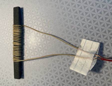
Inductive pickup loop

Shortwave antenna coupling to the pocket or portable is more difficult. A simple clipped wire to the telescoping antenna can greatly increase the noise pickup. If your radio does not have an external antenna jack to safely connect the coax feeder with adaptors then you might have to perform surgery on the radio. Be sure to ground the coax shield to the radio's ground. In any event, be extremely careful if directly connecting outside wire or coax to these modern DSP radios. I cannot stress this enough. You can easily fry the inputs to them. I destroyed a $200 Sangean ATS-909X this way two years ago. Luckily it was still in warranty and I was able to get it repaired and reprogrammed.

NON SHORT-CIRCUITED ANTENNAS

Antennas that are not essentially short-circuited can work but be aware they will capture more noisy RFI. Above ground dipoles or end-fed longwires are two such types. Be sure to use a matching device in any case, which will help.

I hope this has been helpful to you. Please experiment!

Monday, October 12, 2020

Notes On Soft Mute And Analog Tuning In DSP Radios

On the surface, soft mute in the modern DSP-chipped receiver seems a bit mysterious. What is it? How does it work? Why do we have it? In this article we'll explore how soft mute works and explain its technical details.

As a side topic, but somewhat related to soft mute, we'll also tackle the pseudo-analog tuning of the Silabs 483x DSP chip and see what's up there. This is the chip used in many of the cheap portable and pocket radios found today. They are mechanically tuned with a dial knob and have a traditional AM band scale with dial indicator. But they aren't the pocket radio you remember from the old days.

So let's get right to it.

SOFT MUTE

What is soft mute?

Soft-mute is a further lowering of the audio level of the received signal when it drops below a prescribed signal-to-noise ratio. It was implemented in consumer grade DSP radios to provide a more "comfortable listening experience" for the casual listener and not the DXer. The idea is to relieve the listener from all that nasty low level "static" and "interference", or as Silicon Labs states: "....to attenuate the audio outputs and minimize audible noise in compromised signal conditions."

Soft mute attenuation is available in the Si473x digitally-tuned series of chips as well as the Si483x analog-tuned series of chips. The soft mute feature is triggered by the SNR (signal-to-noise) metric. The SNR value is directly readable by the chip's software when you tune to a station. The software reads the quality of the signal through its SNR value and makes soft mute changes accordingly. The SNR threshold for activating soft mute is programmable, as are soft mute attenuation levels, attack/release rates and attenuation slope.

The Tecsun PL-380, PL-310, PL-330, and other radios all may set different soft mute values than the chip's default values shown below. Settings for soft mute are initialized during the power up sequence.

The 4 soft mute parameters: Rate, Slope, Max Attenuation, Threshold.

Rate (default): 278 dB/second (range 1-255, actual figure 278 = setting * 4.35)

Determines how quickly the soft mute is applied/released when soft mute is allowed (enabled). 

Slope (default): 2 dB (range 1-5 dB per dB below SNR threshold)

The attenuation slope for soft mute application - in dB of attenuation per dB SNR below the soft mute SNR threshold. Translated: how much audio attenuation is applied as the SNR and signal quality decreases. A setting of 2 will lower the audio by 2 dB for each 1 dB reduction of SNR below the starting threshold at which soft mute kicks in. An example: soft mute starts to kick in when the SNR decreases to 10 dB. At 10 dB, there is 0 dB of soft mute. When the SNR decreases to 9 dB, soft mute reduces the audio level by 2 dB. When the SNR decreases to 8 dB, soft mute reduces the audio level by another 2 dB (4 dB total). By the time the SNR hits 2 dB, the soft mute has reduced the audio level to a max of 16 dB. It will go no lower as the max soft mute has been applied. Note that every 6 dB of audio reduction is a halving of the audio voltage level. 12 dB of reduction is then 1/4 of the original audio voltage level. 16 dB (max soft mute) is a reduction of 84.2% (0.158).

Max Attenuation (default): 16 dB (range 0-63 dB, max attenuation of soft mute)

If set to 0, soft mute is disabled entirely.

Threshold (default): 10 dB (range 0-63 dB, SNR at which soft mute starts to engage). Silabs states, "for a tuned frequency".

Note that the Threshold setting is applicable only "for a tuned frequency". I take this to mean that soft mute is dis-engaged totally when not tuned to an exact 9 or 10 KHz channel, which is apparently why the 1 KHz off-tuning hack works.

What you're hearing when a signal's SNR lowers below the threshold and the soft mute kicks in is the Slope factor in action. The Slope factor is lowering the audio volume accordingly.

.....

How to defeat soft mute?

Soft mute can be somewhat minimized by increasing signal strengths to the radio by using a directly-coupled loop, passive loop or other inductively coupled antenna. What happens is you are increasing signal levels, thus improving the SNR, making the signal exceed the threshold where soft mute is engaged.

The other (original) hack is to tune off the channel by 1 KHz and raise the volume on the radio. Being off-channel disables soft mute.

.....

Two other interesting parameters effecting tuning and seeking, not related to soft mute.

AM Seek/Tune SNR Threshold.

SNR Threshold which determines if a valid channel has been found during Seek/Tune.

Specified in units of dB in 1 dB steps (0–63). Default threshold is 5 dB.

This tells us that when you do a scan, only stations with >5 dB SNR are eligible to be stored.

AM Seek/Tune Received Signal Strength Threshold (RSSI).

RSSI Threshold which determines if a valid channel has been found during Seek/Tune.

Specified in units of dBµV in 1 dBµV steps (0–63). Default threshold is 25 dBµV.

This tells us that when you do a scan, only stations with >25 dBµV RSSI are eligible to be stored.

.....

THE ANALOG TUNING ALGORITHM

The Silabs 483x series of chips are analog tuned and they have no digital LCD display. Tuning is accomplished through a tuning knob connected to a 100K ohm potentiometer. They attempt to mimic the analog tuning of the old traditional analog superhet radios when you "sweep" through a station's carrier. Silabs has developed a special tuning formula in software to simulate this. From the DXer's point of view it doesn't work. I've given a lot of thought to how their algorithm works in software.

Over the summer here in North America I have bought quite a few of the cheap Chinese analog-tuned DSP Ultralights. Though I have found some can be quite sensitive (like the Sangean SR-35 and the ultra cheap Dreamsky Pocket Radio), the SiLabs tuning algorithm is still wonky and masks a lot of weaker adjacent channel signals. It becomes tedious for serious DXing. Poor selectivity and overload problems can also be evident on these units, depending on the unit.

As stated, the problem with the current analog-tuned theory is that a weaker adjacent channel signal is masked deliberately if next to a more overwhelming signal.

A typical tuning scenario goes like this. Find a strong station where you know a weaker station sits right next to it on the adjacent channel. The weaker station would be strong enough to be received on a normal superhet radio. With the Silabs 483x radio, tune to the strong station's channel. Now tune to the adjacent channel (the weaker station). The strong station is still there, only at a slightly reduced volume. The radio is attempting to mimic tuning "through" a station like in the old days, increasing the strength of the station as you approach its channel center, then decreasing the strength as you depart. But where is the weaker station?

Here is what is happening in software (I think), preventing you from receiving the weaker adjacent channel.

Let's say the following numbers below, 0 | 5 | 20, represent frequencies 1020, 1030, and 1040 KHz. 1020 KHz has no signal on channel. 1030 KHz has a weak signal of SNR 5 dB. 1040 KHz has a strong signal of SNR 20 dB.

   FREQ  1020   1030   1040
   SNR =   0  |   5  |  20

In these DSP radios, hardware generates a tuning interrupt in software when changing the tuning knob. It causes the software to take over and analyze what just happened. 

Initially, tune to 1040 KHz from somewhere above in frequency and begin receiving the strong station.

Now tune to 1030 KHz. Software then does this:

1. The tuning interrupt is generated.

2. Hard mute the audio.

3. With audio off, electronically retune to the new channel (1030) and test the new channel's SNR. If valid (SNR >= 5 dB), remain on this new channel and unmute the audio. If not valid (SNR < 5 dB), electronically retune back to the original channel (1040) and reduce the audio 6 dB and unmute. The dial will point to 1030 even though we're hearing 1040.

Now tune to 1020 KHz. Software then does this:

1. The tuning interrupt is generated. Remember, though the radio dial shows 1030 KHz, the radio is still electronically tuned to 1040 KHz.

2. Hard mute the audio.

3. With audio off, electronically retune to the new channel (1020 this time) and test the new channel's SNR. If valid (SNR >= 5 dB), remain on this new channel and unmute the audio. If not valid (SNR < 5 dB), electronically retune back to the original channel (1040) and reduce the audio an additional 6 dB and unmute. The dial will point to 1020 even though we're hearing 1040.

Additionally, for each of the two scenarios above, we must also be sure in step 3 that the original 1040 channel maintains a SNR above the SNR of the newly tuned channel or we force-tune to the new channel.

Electronically retuning the DSP chip is simply a matter of electronically setting the proper internal capacitance to resonate with the ferrite coil at the desired frequency. It's done with a single software command.

It's complicated.

If you start at 1020 KHz then approach 1030 from below the situation changes, as we are comparing 1030 to 1020 now, 1020 having no signal at all. If 1030 is a valid channel (SNR >= 5 dB) then the DSP chip tuning remains at 1030, the hard audio mute is unmuted, and the station is received. Drawing from this scenario, we can conclude that if we approach a weak signal from the right tuning direction that we might be able to hear it.

Compounding the problem, these 483x chips also generally have soft mute enabled, which may mask very weak stations. The weak station will still need to overcome the soft mute threshold to some degree.

According to Silabs, this new tuning algorithm has been "audience tested" to a positive level of acceptance. The best approach for the DXer would be to have a radio where soft mute is disabled altogether and no tuning algorithm so that when you move the tuning dial it always changes the frequency.

Surprisingly, this wonky tuning algorithm can be somewhat minimized by increasing signal strengths to the radio by using a directly-coupled loop, passive loop or other inductively coupled antenna. What happens is you are increasing signal levels, thus improving the SNR, so the signal meets the threshold requirements for a valid signal. The radio then tunes to the proper signal and frequency.

A description of even weirder analog tuning anomalies can be read here:

Notes On The XHData D-219 Analog DSP Radio

I hope this analysis of soft mute and the DSP analog tuning mechanic has proven useful and interesting. All technical data has been gleaned directly from Silabs data sheets for the respective 473x and 483x DSP chips. The programming guide for these chips was particularly helpful in understanding the operation of soft mute.